About 18 months ago, I purchased a part-built kit for a Shay locomotive. The kit was originally produced by Steamlines (the brass fret is marked “Jan 1990”).
This particular kit was purchased new by Mr Evans of Llangadfan near Welshpool, from Tom Cooper (of Steamlines) on 17 March 1990 as indicated on a receipt in correspondence from the time. It was advertised in “16mm Exchange” (a publication of the 16mm association) of May 2004. Mr Kitchenman purchased it from Mr Evans on 10th May 2004. Mr Kitchenman collected it sometime later on a visit to Wales. When he collected the model it was obvious, sadly, that Mr Evans was in very poor health.
Mr Kitchenman sold it to me in 2020, saying “The only reason I’ve decided to sell is because I find I’ve got too many other loco build projects on my ‘to do’ list“. It was listed in several editions of Throwback Modeller (a publication of heritage steam locos in 16mm scale). I purchased it on 23 October 2020, collecting it two days later at the Bedford Model Engineering Society track. It then sat in my cupboard for 18 months.
Today I put up a large table in the spare room, and set out the loco and parts to see what we’ve got. The main bulk of the loco has been built (it is predominantly soldered brass construction). The two bogies are made up and painted in black. The cab is constructed and painted in primer-red. There are various other parts ready to be installed. Most of the model is still unpainted in brass.
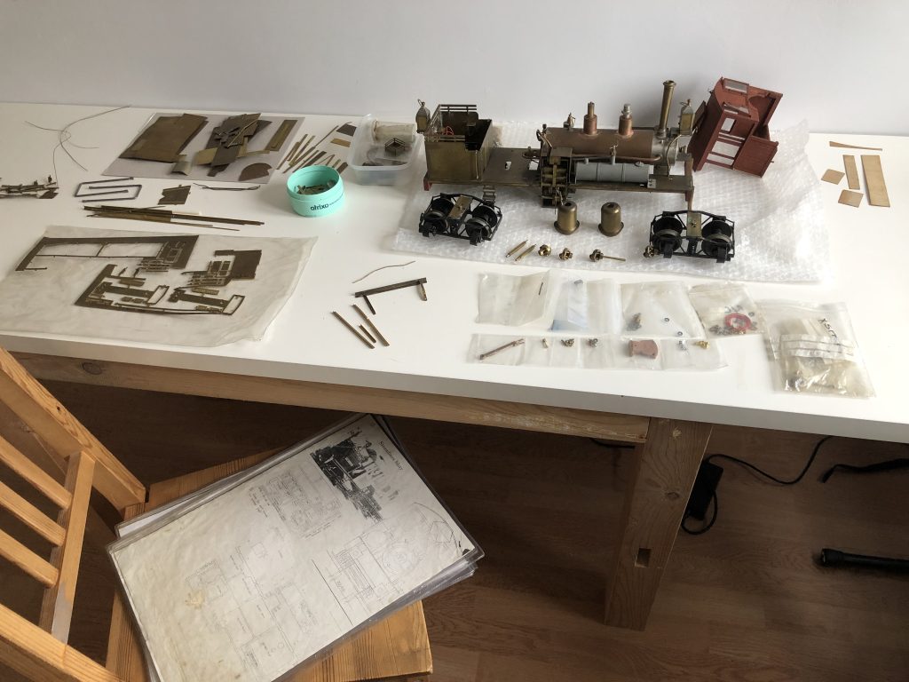
I worked my way through the instructions to get an idea of what has been completed and what is still to be done. There are several A4 sheets on general operation, oiling guidelines, running and steaming. The instructions themselves are on A3 sheets in clear plastic sleeves, as follows:
* Pages 1 and 2 (both on same A3 sheet)
Fret contents and front elevation.
* Page 3
Assembly Instructions overview, advice on bending, paiting, gluing etc.
* Page 4
Step 1, 2, 3: frames (all done)
* Page 5
Step 4 make up bunker (installed)
Step 5 make up sandbox (NOT DONE YET)
* Page 6
Step 6 Bunker light (installed)
Step 7 Servo Assembly (NOT DONE YET)
Step 8 Bogie Mounts (installed)
* Page 7
Step 9 Motor Assembly (pre-built, installed)
Step 10 Lubricator (installed)
Step 11 Servo (NOT DONE YET)
* Page 8
Step 12 Boiler Sub Assembly (mostly installed EXCEPT GAUGE)
* Page 9
Step 13 Banjo from lubricator (NOT YET ATTACHED)
Step 14 Blast pipe bending (done)
Step 15 Blast pipe construction (done)
Step 16 Front Lamp (installed)
Step 17 Blast pipe installation into smoke box (done)
Step 18 Smokebox door (glued on - IS THIS CORRECT?)
* Page 10
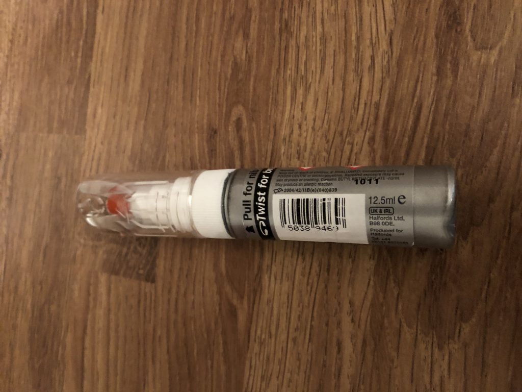
Step 19 Gas tank (pre-painted grey) (installed)
Step 20 Gas Tap (working)
Step 21 Regulator (UNCERTAIN - WHERE IS IT ? )
Step 22 Trial Steaming (NOT YET DONE)
* Page 11 Steps 23,24,25 Bogie assembly
* Page 12
Step 26 Assemble bogie and wheels
Step 27 Over-wheel strip (NOT YET INSTALLED)
Step 28 Couplings (NOT YET DONE)
Step 29 Running in using a bench drill (NOT YET DONE)
* Page 13
Step 30 Mount Bogies on frame (NOT YET DONE)
Step 31 Shafts (NOT YET DONE)
Step 32 Fit buffers (already installed too early)
* Page 14
Step 33 Cab (made up and painted)
* Page 15
Step 34 Boiler Bands (NOT YET DONE)
Step 35 Weight (WHERE IS THIS, AND WHERE DOES IT GO?)
Step 36 Weight diagram (NOT YET DONE)
Step 37 Motor Cover (NOT YET DONE)
Step 38 Gear Covers (NOT YET DONE)
* Page 16, 17
Pages on Radio Control setup
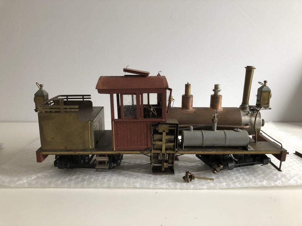
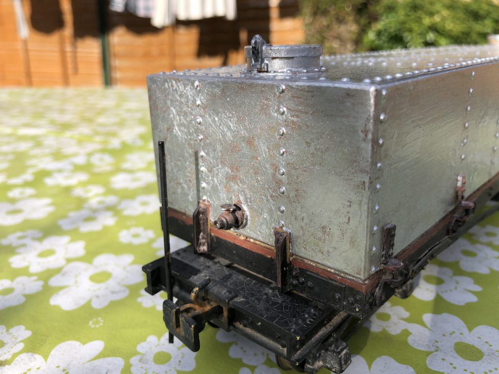
Shay kit as received 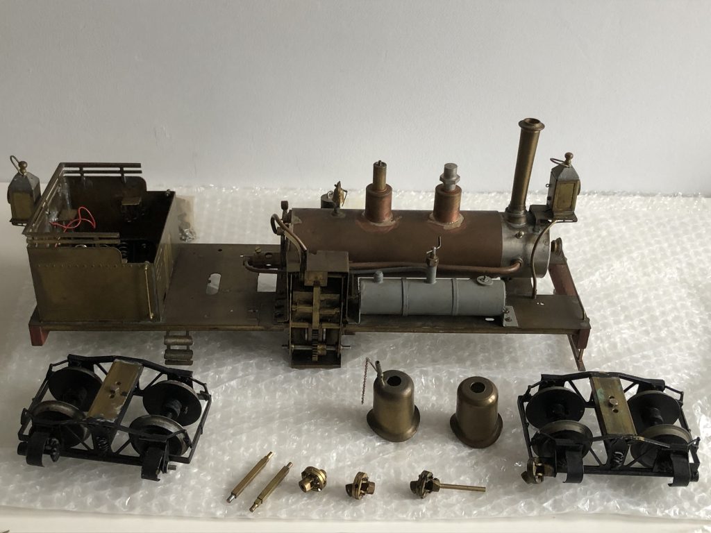
Shay kit as received – major components
Several points to note:
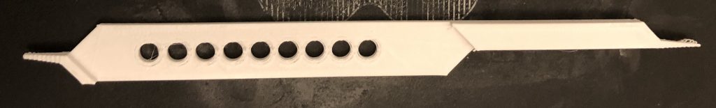
- There seem to have been two versions of the same fret: one thicker than the other. Mr Kitchener mentioned that some parts are duplicated.
- Various bits of fret and brass are left over, which might be useful at some point. Going through these along with the fret contents (pages 1 and 2) I identified a few pieces that have not yet been made up, including the sandbox.
- There are several bags of parts in packaging that look like components from Roundhouse Engineering.
- The kit has not been built in the order of the instructions: for example the buffers and steps are already installed though other major parts have not yet been carried out. The steps up to the cab get in the way of the rear bogie motion.
- I found enough replacement brass angle of the right size to replace the damaged rear buffer beam.
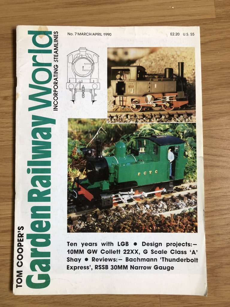
1990 edition of Tom Cooper’s magazine 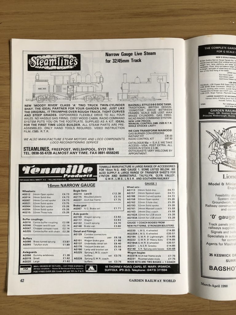
Original advert for the 2-truck Shay 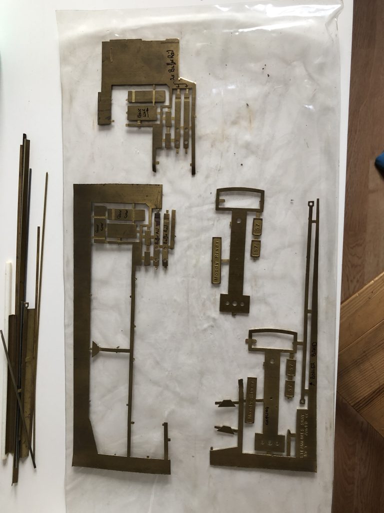
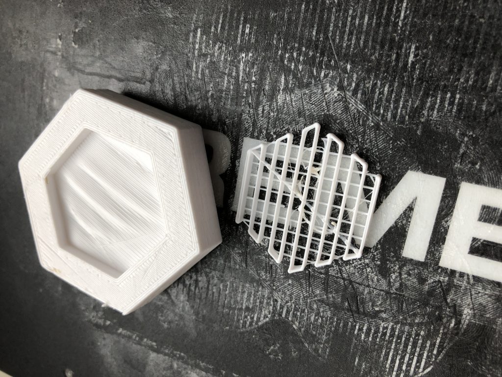
Duplicate fret parts
Justin – 27 April 2022