The idea
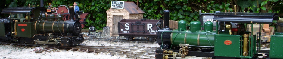
This photo is not the caffeine shelf. It is an earlier project – the hexagon shelves that I made in February 2021. I was talking to someone about it. They suggested I should make one along the lines of the structural formula (wikipedia) for an organic compound, and showed me a picture of the Caffeine molecule (wikipedia). I was intrigued. If I can cut things at 60 degrees for a hexagon, then I can cut things at whatever angle is needed for a pentagon as well.
The inspiration
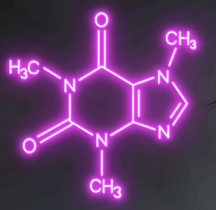
A quick look on online shopping sites will reveal lots of inspiring ideas. The image on the right is for a neon display of the Caffeine structural formula, which my client found on Etsy.
I chose to ignore the detail of the lettering for this project, and just concentrate on the lines. For the curious, they represent single and double chemical bonds. Learn all about them on BBC Bitesize.https://www.bbc.co.uk/bitesize/guides/zj38scw/revision/3
The maths
It can’t be difficult. In fact it should be easier than the hexagon shelf because this one has less parts. There are 6 sides of the hexagon, five sides of the pentagon (one side of each shape conveniently doubles up to form the double bond) and seven spiky sticky out bits (spoiler – scroll to the bottom to see what I mean).
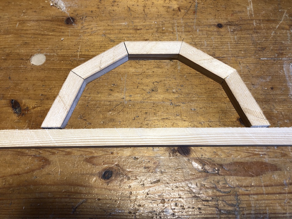
A hexagon has six sides, and the angle I cut for a hexagon was 60 degrees, which is 1/6 of 360. So I assumed that I would need 1/5 of 360 for a pentagon. So I cut a few test pieces at 72 degrees … and found they create a half-circle. What went wrong?
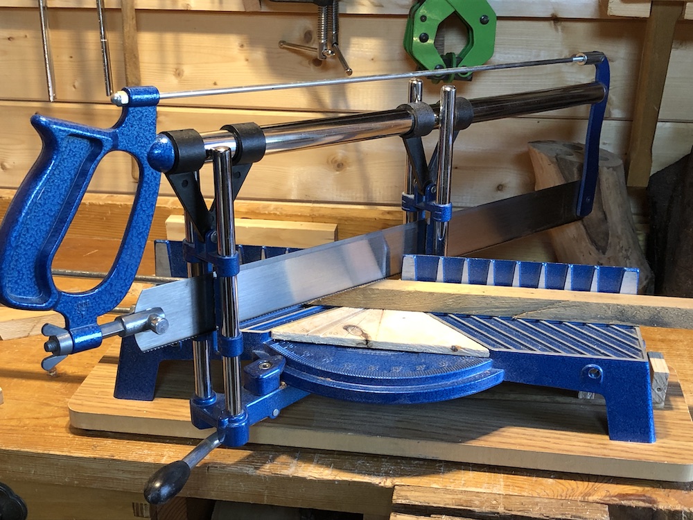
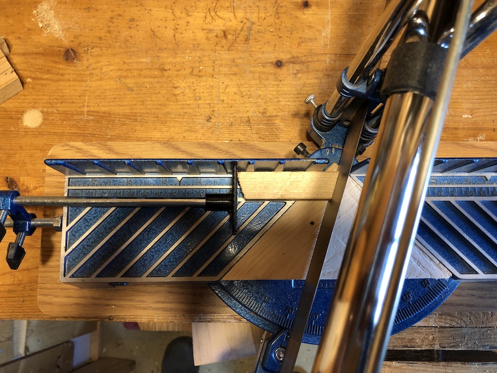
I am using my hand miter saw to cut the parts.
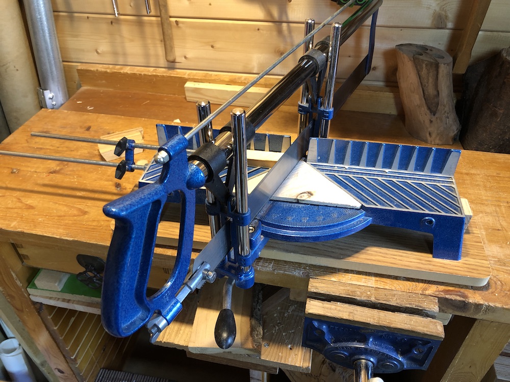
A 90 degree cut gives a square end to the piece of wood. A 60 degree cut at each end is used to create the hexagon, and a 72 degree cut at each end creates … well it creates the half-circle above.
… and thus I realised that I am not cutting six angles, but twelve (one on each end of each piece of wood, and there are 6 pieces of wood). I did twelve cuts for each hexagon, so it should have been obvious.
The actual maths for a hexagon is therefore:
90 degrees (a perpendicular cut) – (360/12)
Which happens to conveniently give me 60 degrees.
So the maths for a pentagon is:
90 degrees – (360/10)
… which is 90 – 36 … which is 54 degrees. So I cut some test pieces, and ta-daa I have a pentagon.
Assembly
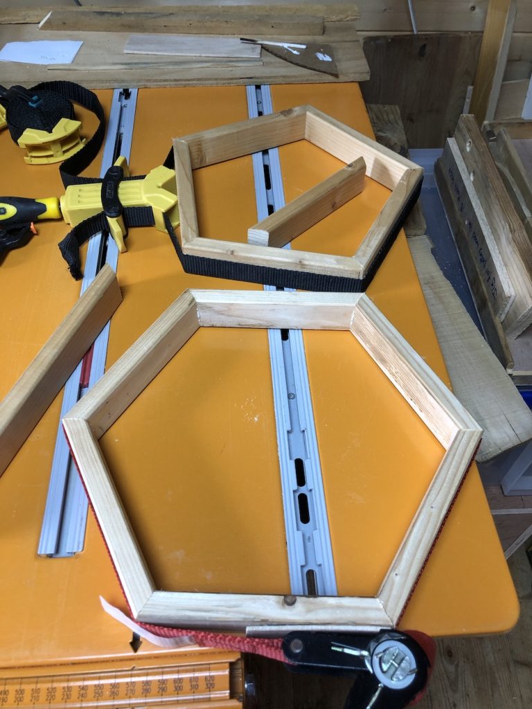
Once I had cut the pieces to the right angles … and cut some of them again because I set the miter saw up incorrectly … I just needed to glue everything together.
For the curious, I am using Evo-Stik outdoor grade wood glue. The yellow box clamp is really useful for this sort of project. A ratchet strap (red) is a reasonable substitute, but the yellow one is much easier to work with. The orange work bench is a Triton Workcentre 2000 table saw (with the blade retracted all the way down).
I forgot to take photographs of the round spacers. If I remember, I will add them to this post later on.
The result
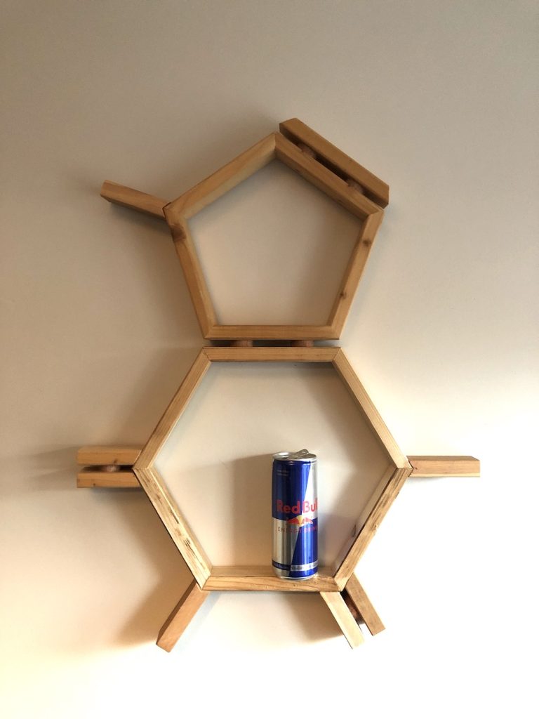
So here is the caffeine molecule, on the client’s wall, with a suitable caffeine beverage for scale. The parts are simply glued together with wood glue. The separators between the double bonds are circles of a darker wood, cut out with a hole-saw. I made brass mounting brackets (hidden behind the upper part of the hexagon).
The convention for drawing the caffeine molecule is horizontal, i.e. rotated 90 degrees from the way I have mounted it. However this is merely a convention, and this vertical arrangement is much more practical – there are actually some horizontal surfaces.
If you really want to scare your friends, you can call caffeine by its technical name, “1,3,7 tri-methyl xanthene”. You’re welcome.
Project started end of March 2024 and completed 3rd June 2024. Let me know what you think: Justin at wis.co.uk.